TreeHacks 2026 Badges
The journey of designing, testing, and manufacturing PCB badges for the largest collegiate hackathon in the world.
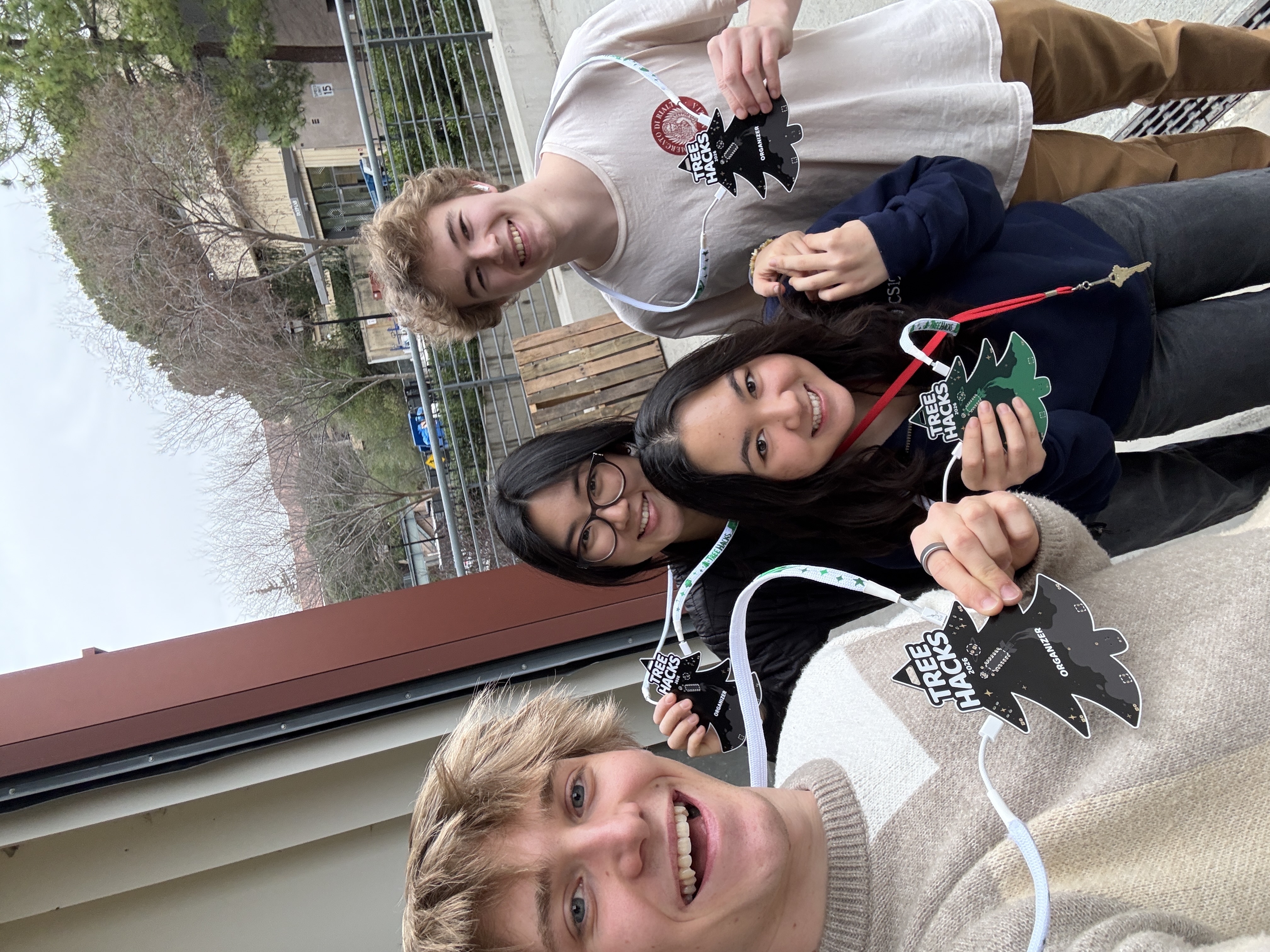
One of Stanford's core traditions is the "roll out," where clubs announce your acceptance by pounding, screaming, and shouting at your door between 5-6AM, waking up everyone else in the dorm. Then, to make up for the embarrassment, they take you on a small journey—usually to a restaraunt. This is how my first day of TreeHacks went.
After our breakfast, I thought about what my acceptance meant. I assumed I'd play just another small role in organizing; I would be part of the tech team, taking orders to build this and deploy that. What TreeHacks actually let me do, however, was far cooler.
TLDR: I wrote firmware for our thousands of badges, designed my first fun-oriented PCB, coordinated a sponsorship, spent hours nitpicking in Figma, orchestrated component sourcing, sent angry emails, and much more. Unlike most TreeHacks projects (known as “builds”), I was the sole person working on our badges this year.
Design
One of the most difficult design choices in the beginning was what I even wanted the badge to do.
Definitely LEDs. Should I put a buzzer? What about a matrix of LEDs that doubles as a spot for people to display their names?For a week or so, I went on a cat-and-mouse game of inventing ideas, finding components, and checking budget constraints. There were some really cool ideas, like the aforementioned LED matrix, that had to be scrapped due to component costs and manufacturing complexity. As shown below, the badges ultimately wound up with an externally driven buzzer and 6 LEDs—what I thought was a perfect balance of customization and complexity.
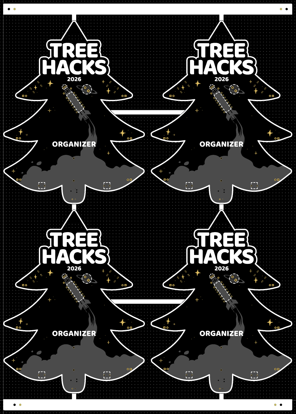
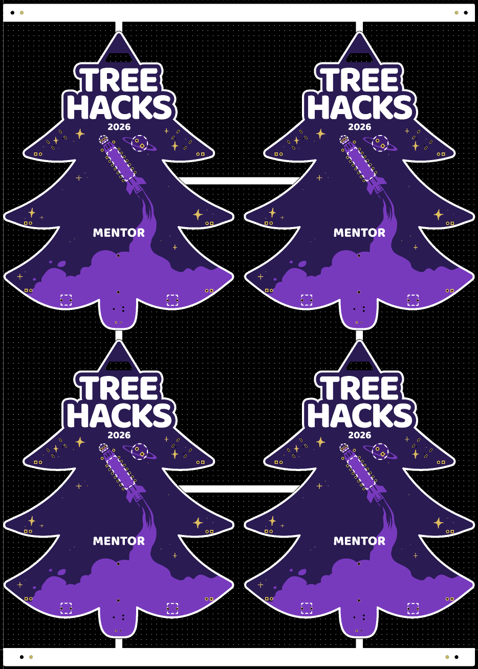
The edge cuts of the badge (its shape) is the tree found in the TreeHacks 2026 logo. The design found on the badge itself, including the rocket and assembly instructions, was made in Figma with the help of our design team.
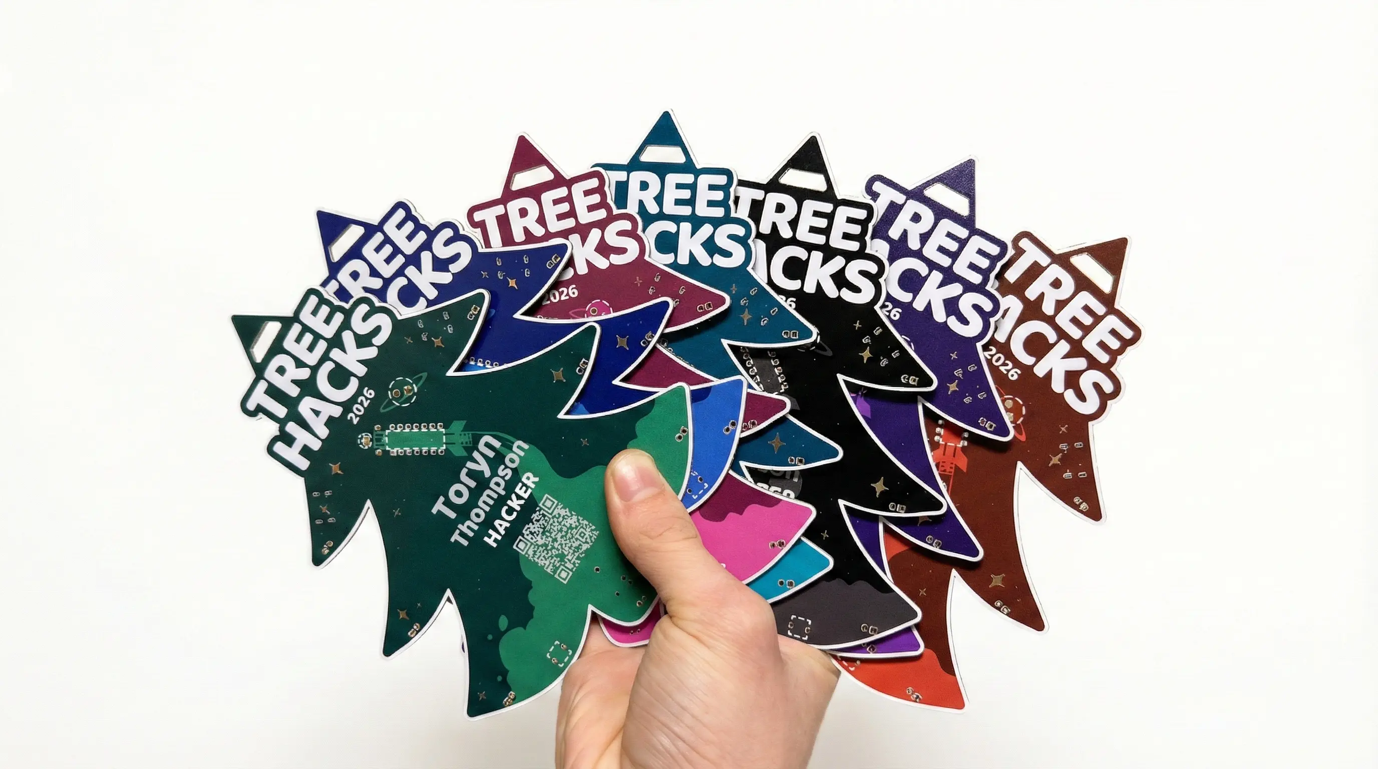
Contrary to what you might think, the printing of the design is actually not silkscreen. In fact, there is no silkscreening on this entire board. We used JLCPCB’s “Multicolor Silkscreen” manufacturing option, which in reality just means UV printing. To achieve this, I had to import the design into JLC’s EasyEDA software and painstakingly align it to the board for each differently-colored design, yielding us 7 different types of PCB badges. Here are my two personal favorites: organizer and mentor.
Schematic
The PCB schematic was a little tricky. While it mainly involved rummaging through datasheets to find the appropriate microcontroller pins for each item on the board, I kept fighting myself about how much I would have people solder; I desired the absolute minimum.
One of my initial tactics was driving the buzzer without a transistor, but this failed because its peak current draw reached 100mA—far above the 50mA max of the PIC16 microcontroller I chose. Similarly, the original design had 6 differently-colored LEDs. However, with all the different voltages required, this would mean a lot of resistor soldering, so I ultimately made them 3V green and blue LEDs.
Another consideration was battery life. While I wanted the LEDs to run continuously, this would drain the 220mAh CR2032 powering the badge within a few hours. We didn’t want to buy thousands of batteries to act as replacements throughout the event, and we also thought the likelihood of people coming back to replace their battery during hacking was pretty low. This led me to add two buttons: one for the buzzer and one for the LEDs, allowing them to be activated when desired.
I also spent significant time deciding which microcontroller to use. My primary considerations were that it was easily programmable and had enough pins to drive 6 LEDs, a buzzer, 2 button inputs, and a photodiode input. I didn’t know exactly what peripheral capabilities I wanted other than at least two timers, but the Microchip PIC16F1503 I chose continually met requirements that came up later, so I stuck with it.
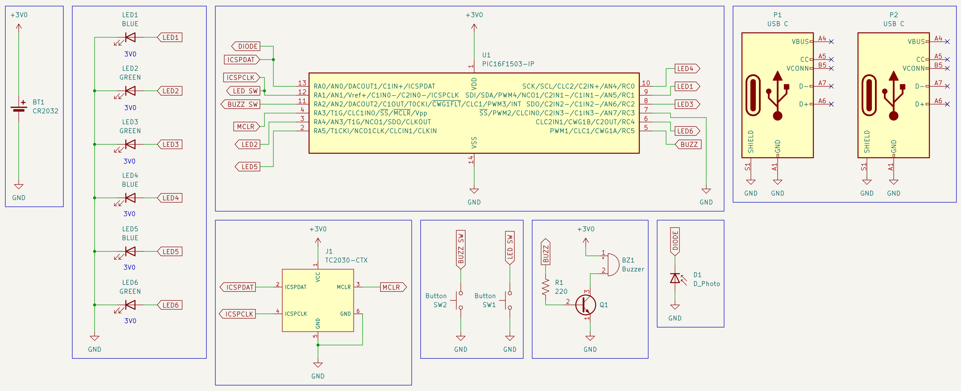
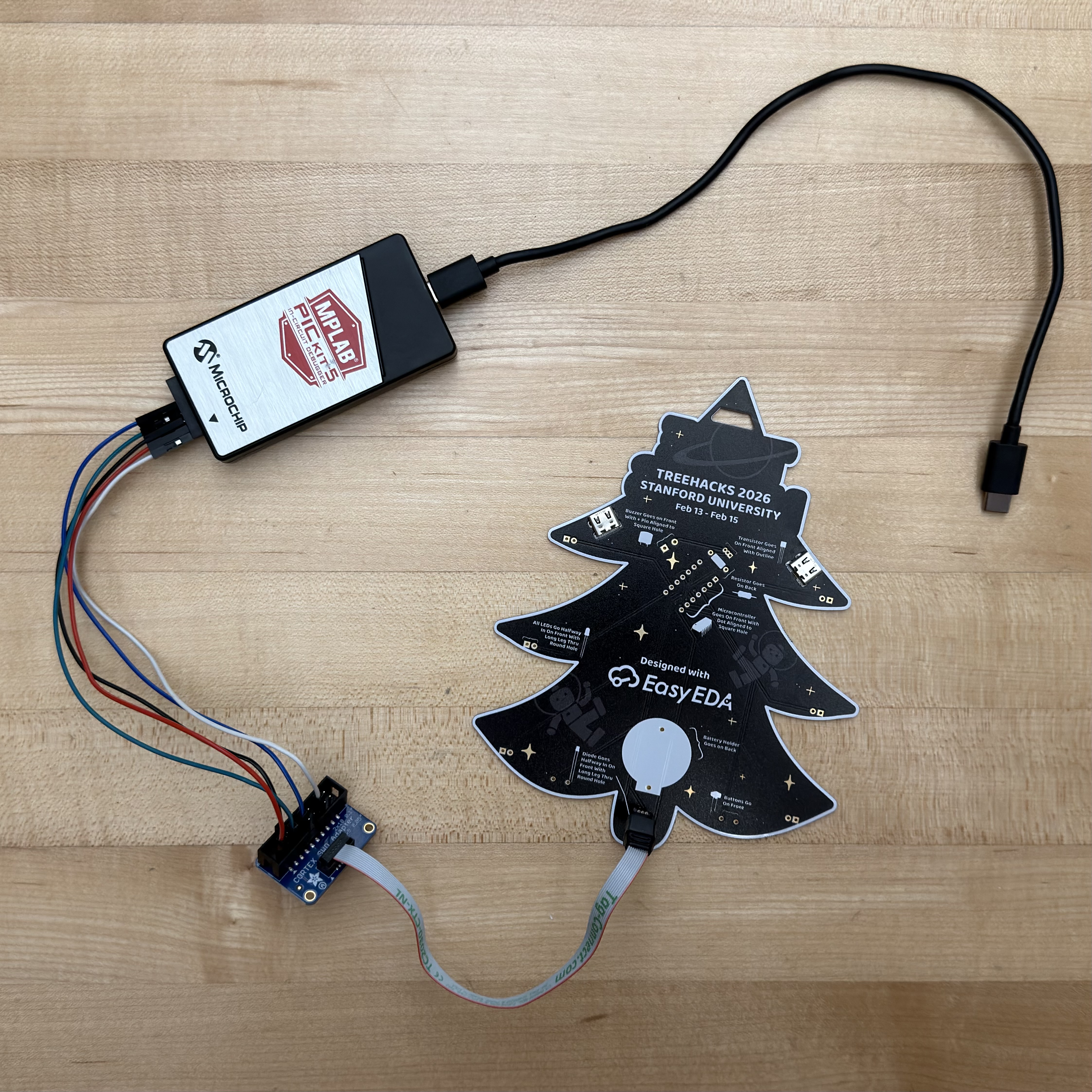
If you’re curious, the TC2030-CTX symbol is a Tag-Connect debug header located on the back of the PCB. This allows me (or you!) to re-flash the microcontroller using Microchip’s PICkit 5 and a setup that wires an appropriate Tag-Connect cable to it.
Here are some of the breadboards I used throughout my testing.
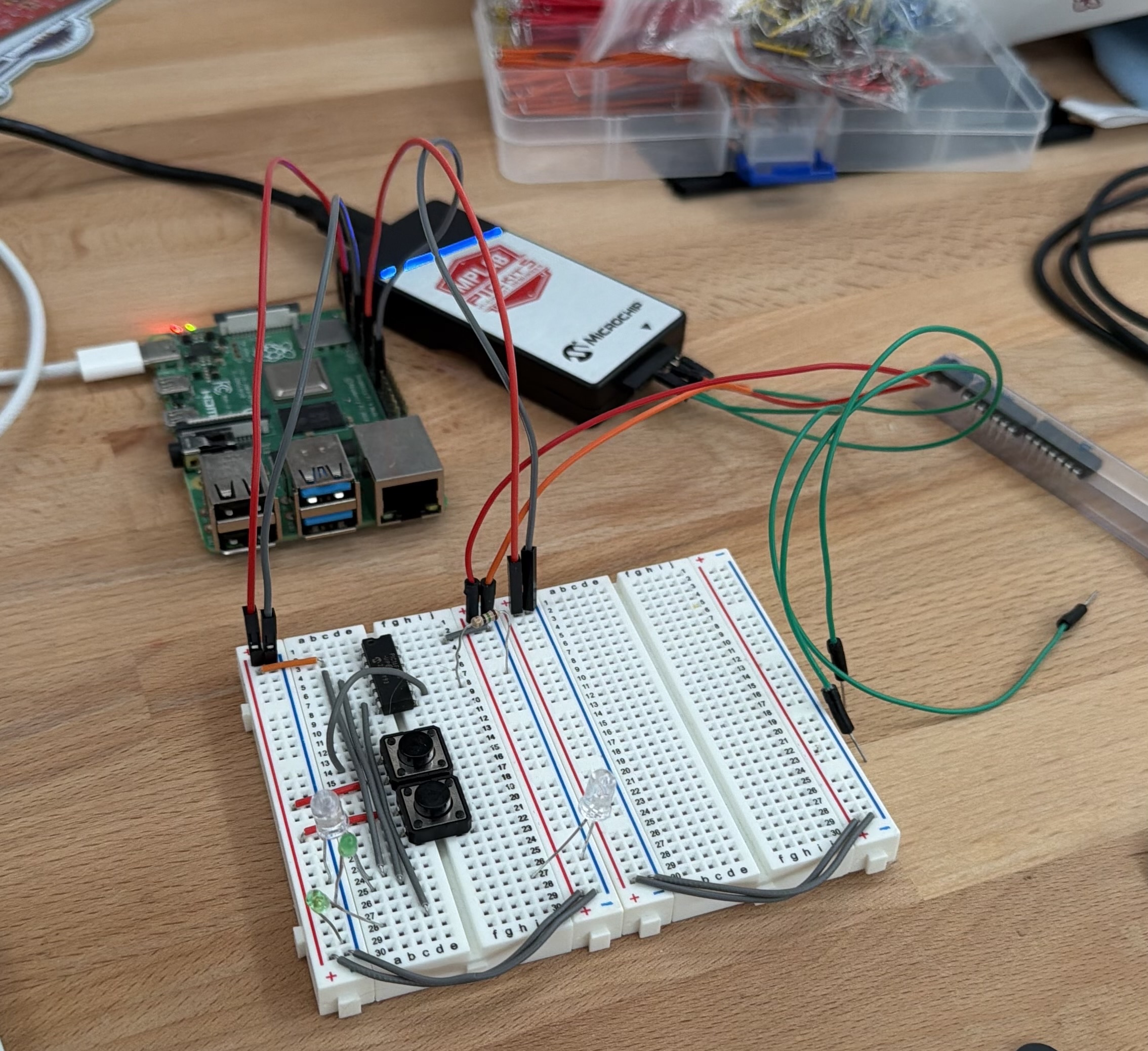
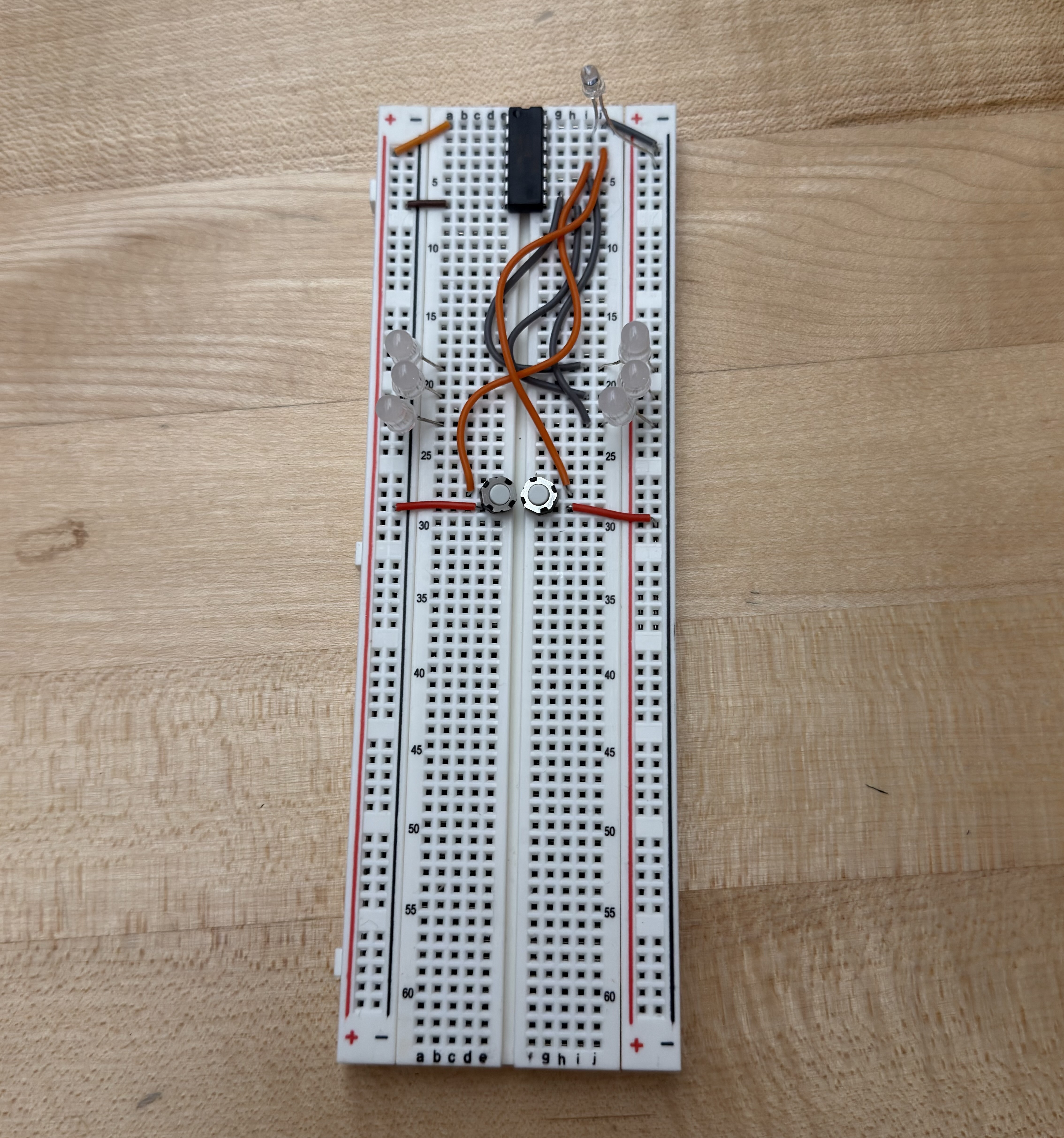
These ended up being the bane of my existence, as the extra capacitance caused major issues with my photodiode testing.
Lanyards
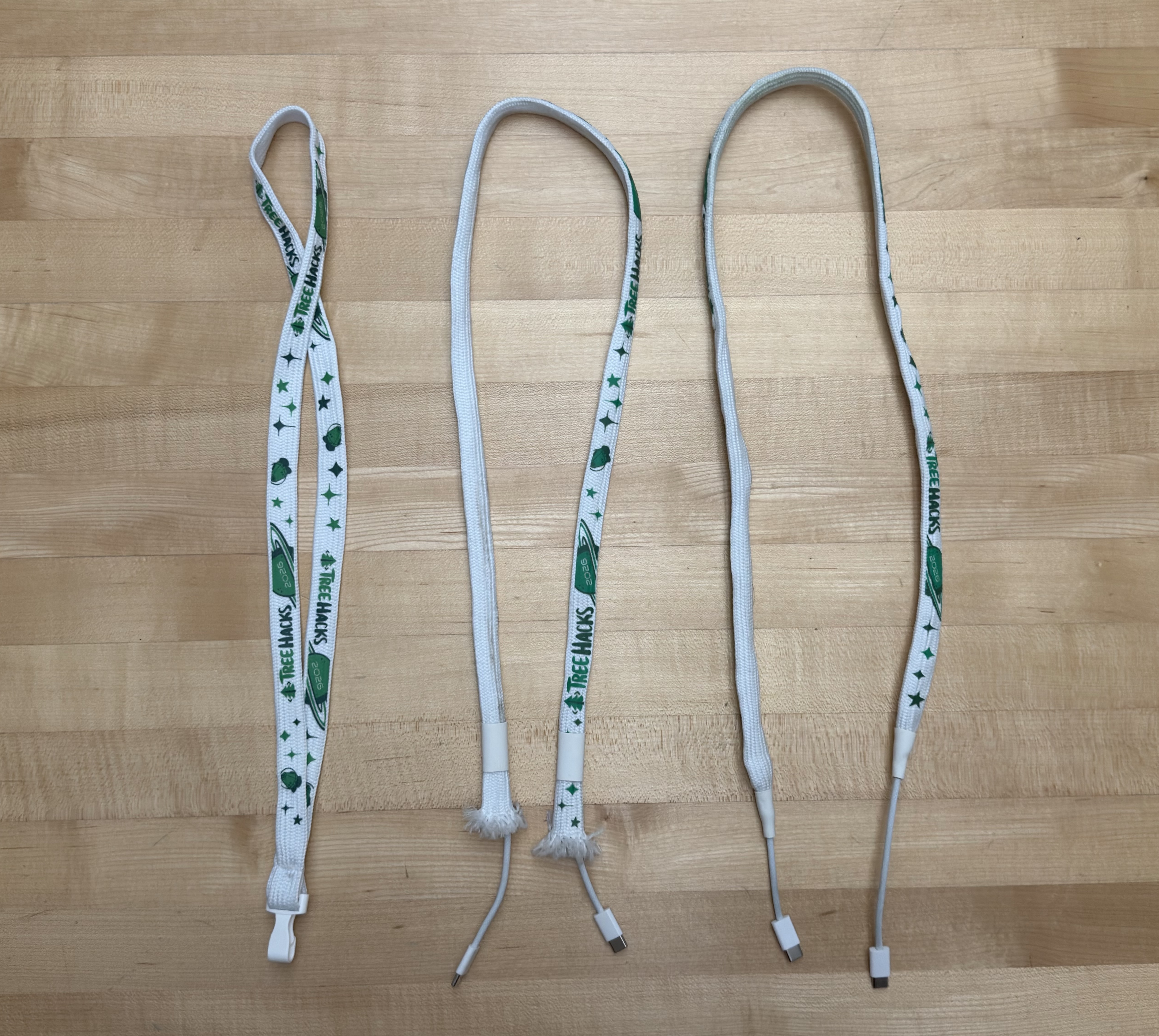
This is also around the time I came up with the idea for the USB-C lanyards we had this year. While we couldn’t be the first event to have PCB badges, I could make TreeHacks the first mainstream event to have cable-based lanyards.
Originally, they actually weren’t USB-C. Worried about the connectors falling out, we opted for Ethernet-based lanyards. We would buy thousands of feet of cable, wire it through tubular lanyards that have the end seam cut off, and then crimp the ends!
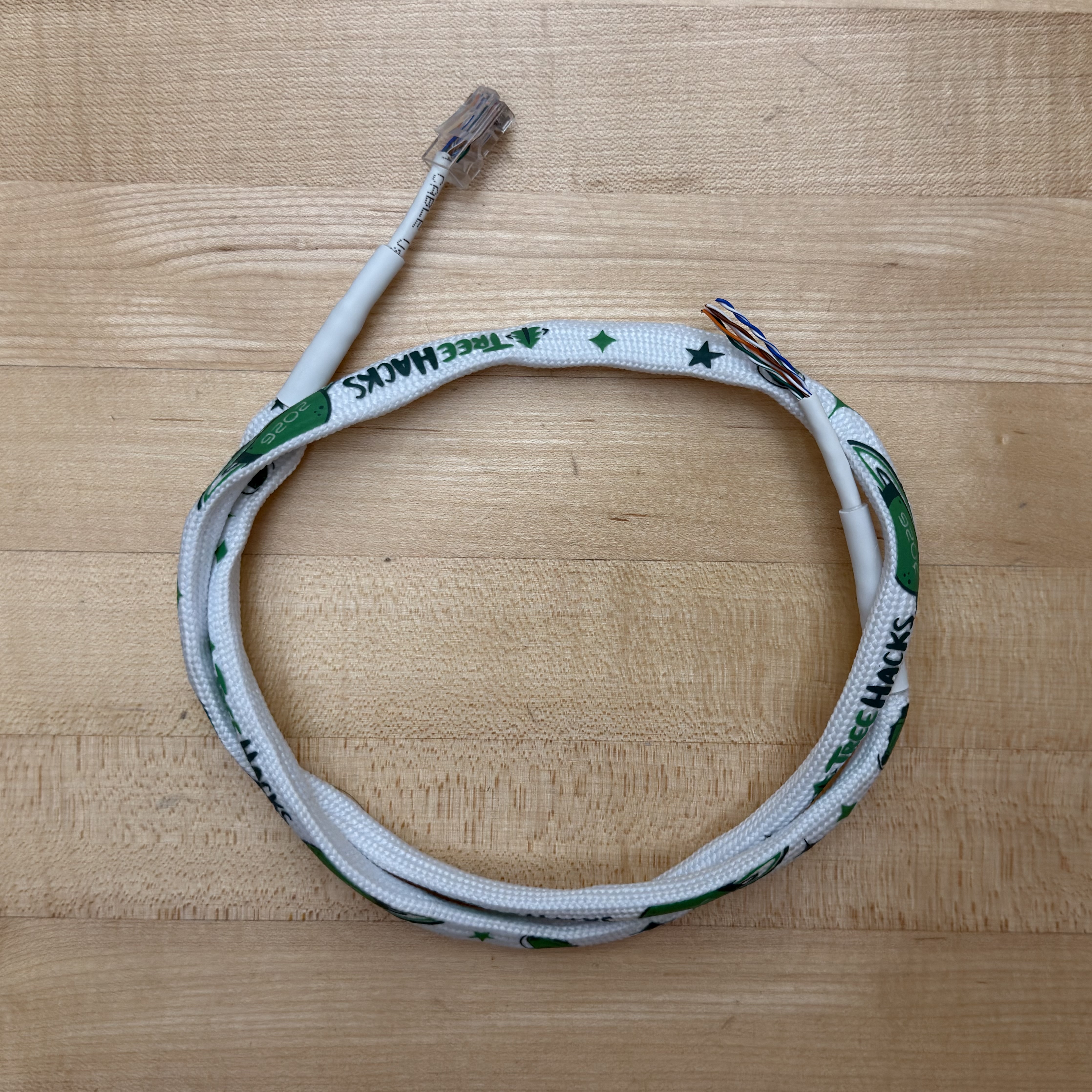
The problem: this takes a longggggg time. We needed to make around 1000 custom lanyards to accommodate all of the hackers coming. Assuming each takes 10 minutes—which is generous for people doing hundreds of these while crimping Ethernet cables for the first time—a 10-person subset of our team would still take 16 hours straight.
So after our 3rd meeting with no solution, I tried my luck. I plugged one of my USB-C cables into a TI demo board and shook it around violently. I then hooked last year’s OpenSauce badge around one of the feet and re-conducted my test. To my surprise, it stayed!
After finding a few manufacturers—one for USB-C connectors, one for cheap USB-C cables, and one that could provide me 70m of pre-cut shrink tubing—I was set. We had already found a good manufacturer for tube lanyards.
Firmware
Now the really fun part: firmware! This was by far the most time-consuming component of these badges, mostly due to my unfamiliarity with the PIC16 and Microchip’s suite of firmware development tools. I knew early on that I would have a loop that progressed through the frames of the LED and buzzer sequences if their respective buttons were held down—that was relatively easy. The issues arose when I wanted people to be able to customize their badge by programming it through a photodiode, a feature inspired by the OpenSauce 2025 badges.
Naturally, you may wonder why I didn’t opt to use the USB-C ports on the badge for programming. The primary reasons were cost and complexity. I would need a separate USB controller IC and a custom serial driver that communicates between the badge and live.treehacks.com. Now imagine doing all of this, but also making it mobile-compatible for ease of use. The photodiode was a clear winner if I could get it working.
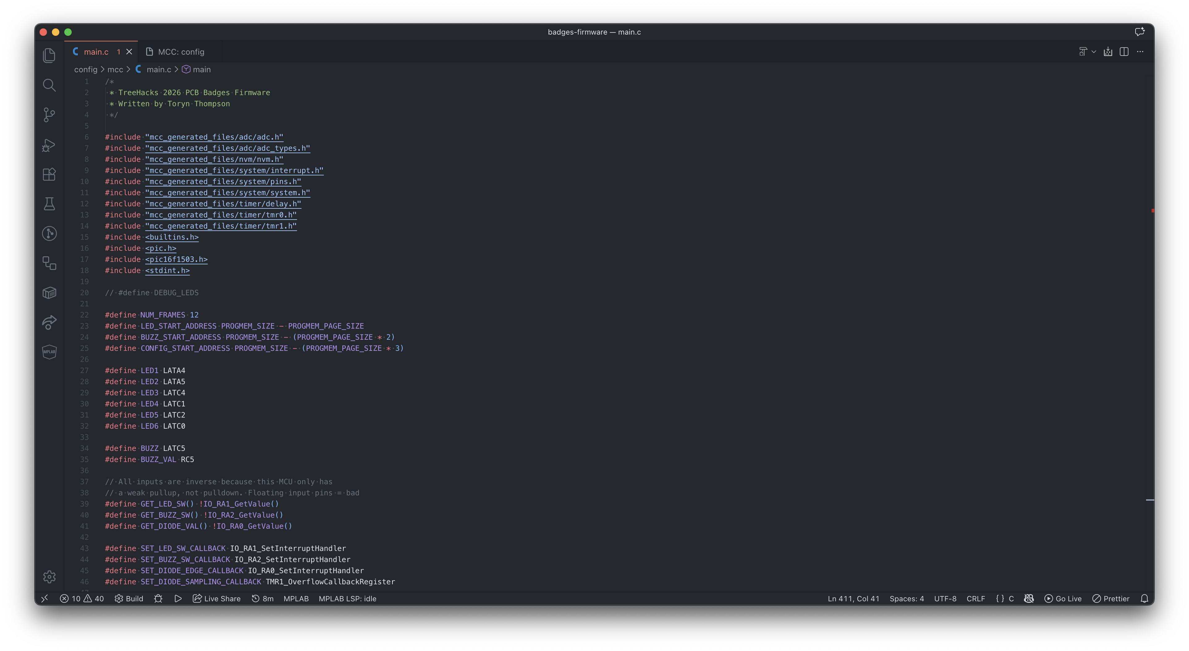
If you want to look at the code in its entirety, it’s on my GitHub.
I could walk through a lot of the decision-making in my code, but for the sake of this post, I’ll keep it to the most interesting part: the photodiode-based programming.
Let me start with a high-level overview of how I wanted the programming to work: A special web page would allow you to customize the LED and buzzer sequence, encoding it into a series of bits represented via black and white flashes on your screen. The black and white act as edges for the photodiode, as the additional screen brightness of the white allows more current to flow through the diode, thereby dropping the voltage on the cathode that is connected to a pulled-up GPIO input. There would be 6 bits for each LED frame and 3 bits for each buzzer frame. A start sequence to activate programming mode would also be needed, and, importantly, it would need to sync the clocks of the two devices.
That’s it! Initially, I thought I could get away with treating a photodiode like a switch, meaning I could simply attach its cathode to an input pin to detect any edges. Unfortunately, because modern phone screens are not that bright relative to the sources most photodiodes are made for, this wouldn’t work. The voltage wouldn’t drop significantly when using the flash baud rate of 10 that I wanted.
This led me to use the PIC16’s ADC module, as it would allow me to measure the exact relative voltage of the pin. The final product weakly pulls the pin up, stops, then measures the remaining capacitive voltage in the pin after 400µs, which I found was enough time for even pretty dim screens to fall below a threshold that wouldn’t occur naturally. There was a lot of testing of different photodiode types and redundancy algorithms that I’m skipping over here, but another interesting key motivator of the 400µs delay is phone screens’ PWM dimming, which would occasionally drain the capacitance at a slower rate even when sustaining the same brightness. I assume this is due to the diode catching the screen being “dark,” as the PWM period of even modern phones is often greater than 400µs.
You can see the drain visualized by this oscilloscope; though, the issue due to PWM isn’t visible in this particular photo.
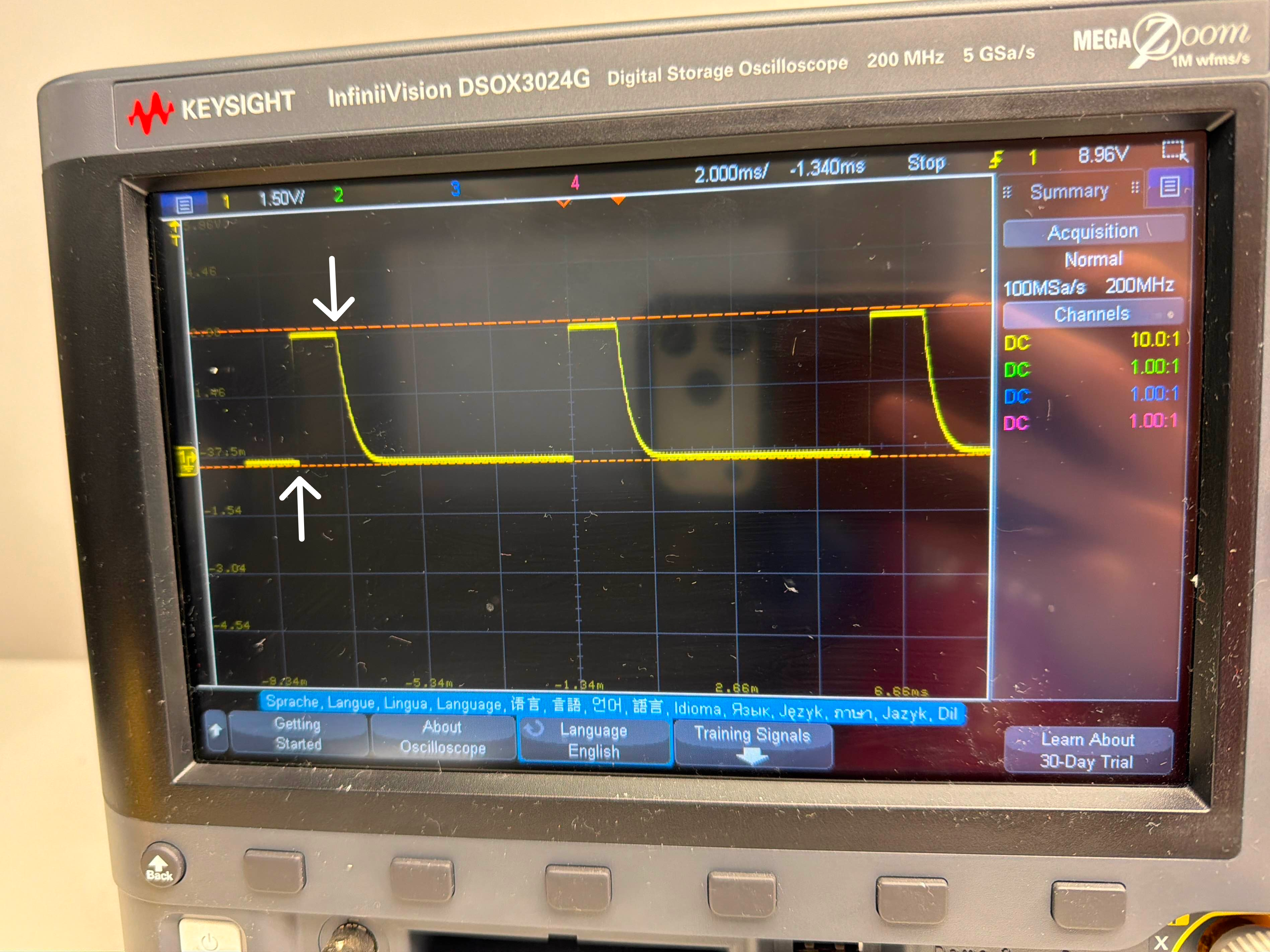
The two arrows indicate where the weak pullup is activated and then deactivated. In this case, a lit screen was being held up to the photodiode, draining the capacitance.
The start sequence detector looks for 6 consecutive high-low or low-high edges, with the period of these edges being measured using a timer counter. This allows for theoretically any baud rate, as the baud rate is dynamically measured each time. As long as it is not faster than the delay of reading the diode plus the execution time between measurements, it should work.
Another note here is that we want to account for the diode possibly missing some of the black and white start flashes, since the user could bring the diode up to their phone screen after hitting “program.” This is why the website actually flashes more than 6 times. This means we need to differentiate between what is actually data and what is still the start sequence after 6 flashes, so what truly begins the programming is 4 consecutive highs (black squares), paired with a final low (white square) that signals the next period will be the first bit of data. The data is then read and, boom, programmed!
You can find this flashing tool on live.treehacks.com/badges. If it's not 2026 anymore, this might not be there anymore.
It can be a little finicky, so if you made one of these while at TreeHacks 2026 and your program doesn’t properly transfer the first time, try it again. Moving the diode closer or further from the screen can help; there’s usually a sweet spot for every screen to match the pre-programmed threshold value that determines whether it’s reading a 0 or a 1.
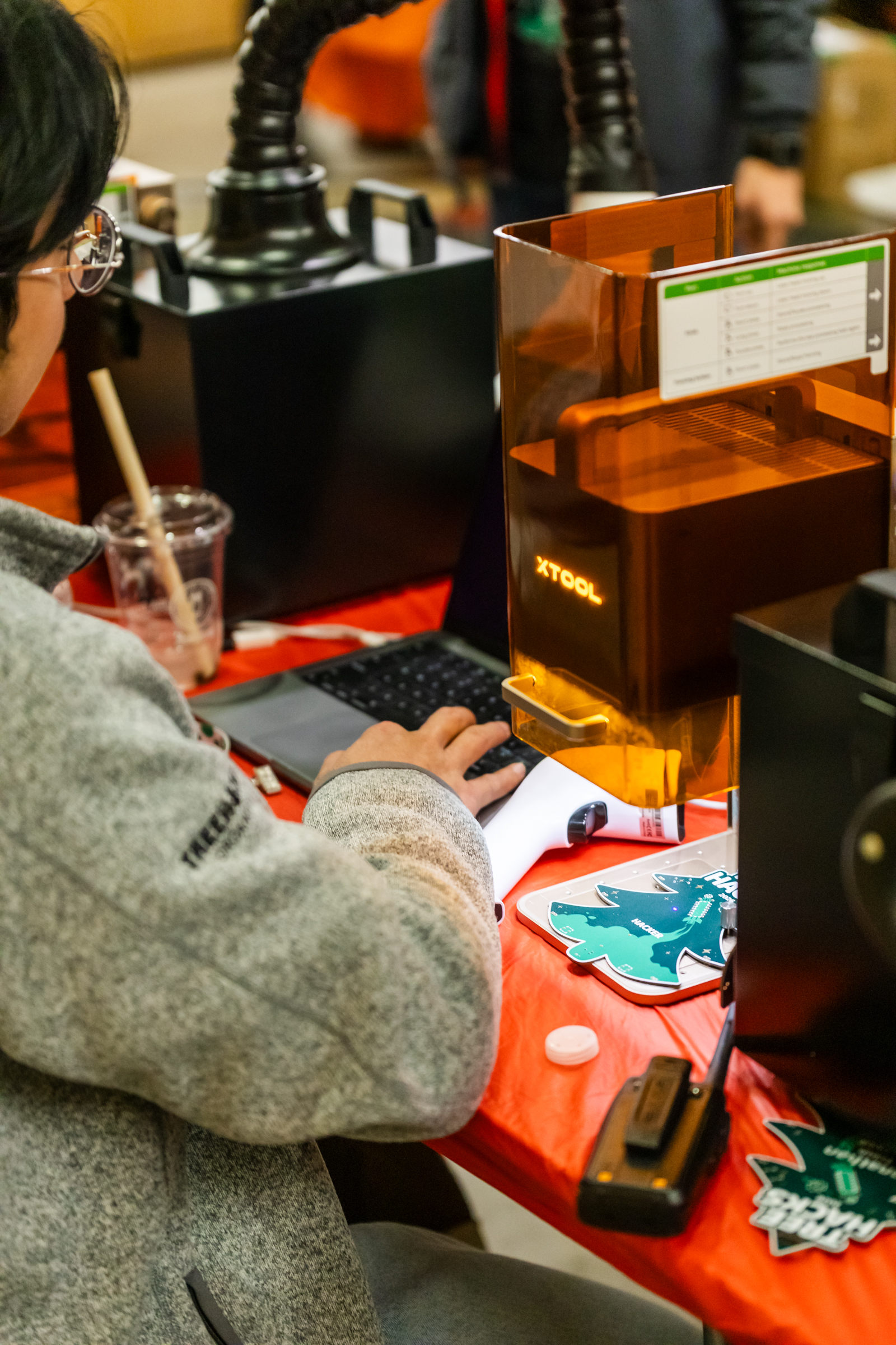
Lasering Names
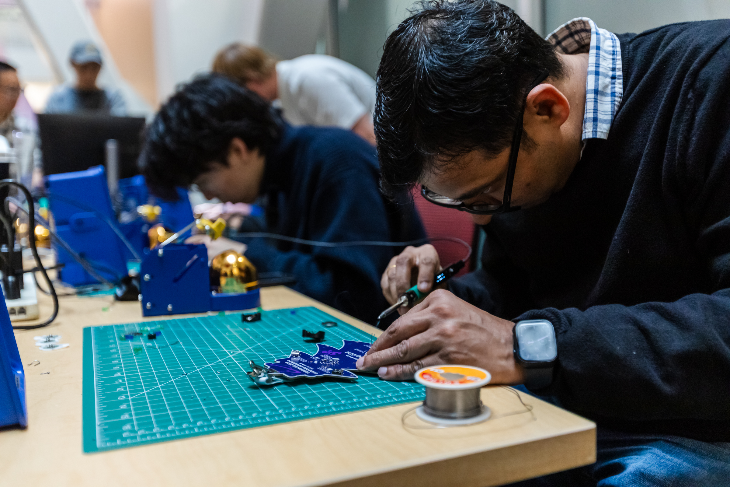
Historically, TreeHacks has always had names and QR codes on its badges, the latter being a requirement for getting around the event. I knew this would be a pain point for PCBs because no manufacturer would ever individually silkscreen PCBs with names on them, even if using UV printing. So I resorted to the next best (and cooler) option: lasers.
Originally, due to time concerns, we wanted to pre-laser all of our badges so they were ready to be retrieved during check-in. This is what we have done in all previous years of TreeHacks. To achieve this, we tried working with the local makerspaces here at Stanford. However, weirdly, nobody wanted us to shoot their laser at thousands of PCBs containing some mysterious, undisclosed UV ink and other chemicals. So we bought 3 400x880mm DIY laser kits from AlgoLaser instead.
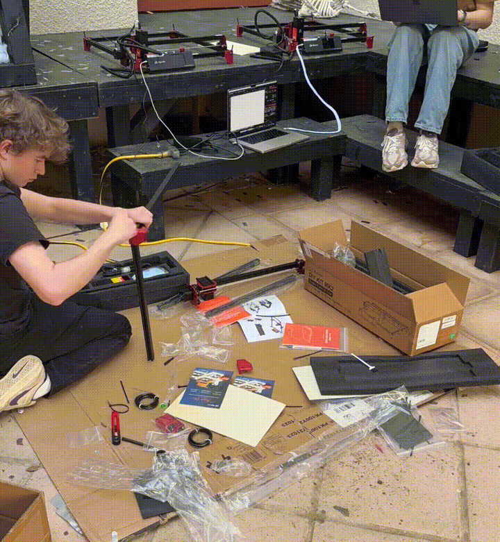
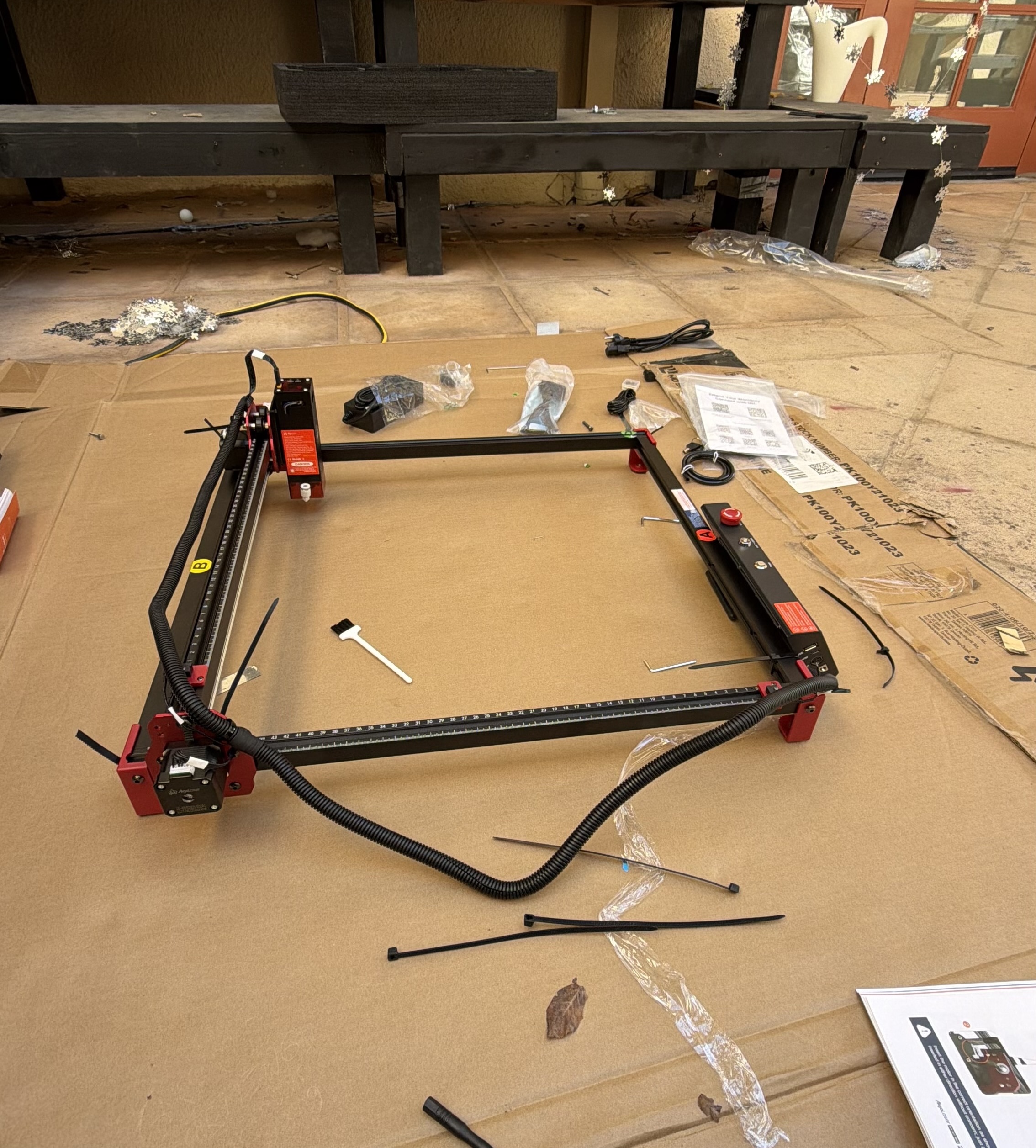
Unfortunately, these lasers had a major issue. While the laser itself worked fine for our purposes, the belts that allowed the laser to traverse would frequently slip, no matter how much I tweaked their positioning and tightness. I couldn’t tell if they were expanding and contracting due to temperature fluctuations—which would always be an issue since we were conducting this outside—or if this was a skill issue. Either way, nobody could get them working consistently.
This is when the tech co-director, Thijs, mentioned he had his own mirror-based UV laser that he was willing to try. It worked like a charm, even without the settings tuned.
After a few more iterations of laser settings, we had a fast, reliable way of lasering on people’s names right after they checked in.
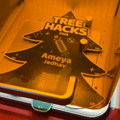
The GIF shows a name being lasered over someone else's because it was a test.
A Working Badge
There are many smaller details I’m skipping over here for the sake of length, but I would encourage you to reach out if you have any questions! All in all, this was a super fun project, and I hope those of you who attended TreeHacks 2026 hang your beautiful badge somewhere. If you’re really ambitious, I’ve linked all of the necessary components at the bottom, and you can order them and build it yourself—assuming you have a way of flashing the microcontroller.