hardware + firmware · 2026
8x8x8 Music-Reactive LED Cube
a 512-LED cube using a custom PCB and firmware for different 3D FFT visualizations
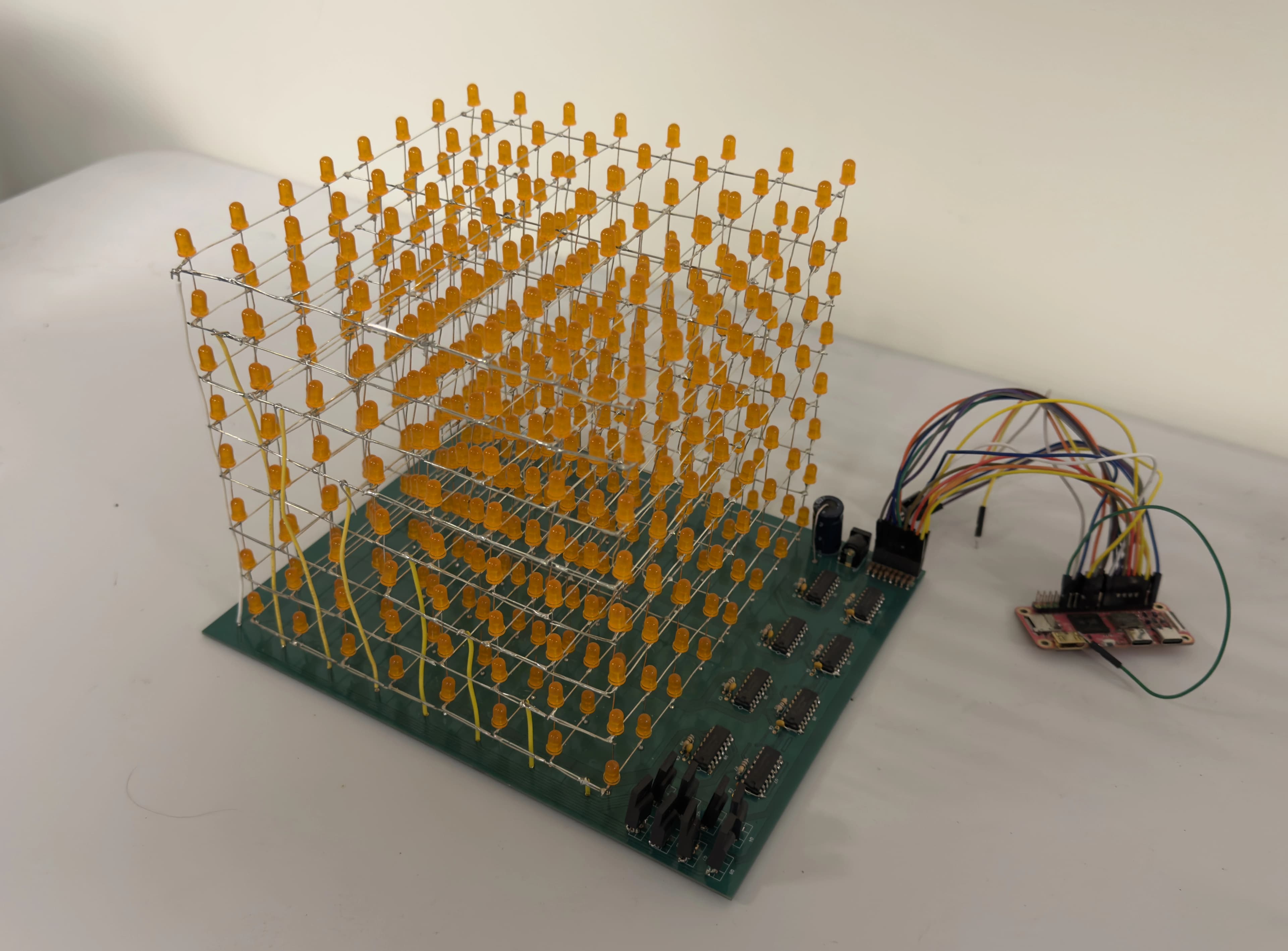
I've always loved music visualizations. When I was younger, I would watch the NCS videos and wonder how they created those orbs that reacted to sound. Into middle school, I became a big fan of the directing on YouTube channel Lyrical Lemonade, which primarily does Rap music videos. Then, in high school, I did audio engineering for our theatre, and thought the frequency charts were just so interesting.
With that, it was more a matter of "when," not "if," I was going to build my own visualizer. So when my CS107E class at Stanford announced a final project, I knew exactly what I wanted to do.
TLDR: In just 2 weeks, my project partner Andrea and I chose components, designed a custom PCB, hand-soldered 512 LEDs into a cube, developed custom drivers, and wrote an FFT algorithm alongside a physics simulation in bare-metal C. The result was an LED cube that reacts to any nearby audio, with selectable visualizations: bucketed frequences in a categorical chart or bulging planets that spin around one other.
These videos show just the bucketed frequencies. The video at the end of this article shows more.
ideation and initial design
It took Andrea about 3 minutes of going through ideas for our final project before I finally piped up and said,
"What if we make a 10x10x10 LED cube."Andrea, after giving me the you're-an-idiot look, said 1000 LEDs is too many. I kept pushing, though, and dropped it to 8x8x8.
"What about 512 LEDs?"Entertaining my idea, we walked throught the multiplexing required. If we sliced the cube horizontally and connected the edges of each 8x8 plane all to the same shared grounds and power lines, we would only need 8 grounds and 8 power lines, which could fit on our GPIO.
However, this meant each LED got of the time if we refreshed at a frequency of . If we want to be relatively smooth and go for 60fps, this means each LED is ON for ~260µs. This would make our brightness ceiling very dim to the human eye, and we wanted the cube to be visible under light. Additionally, the wiring would be messy, and each layer's supports would be on just two sides of the cube.
Our solution: 64 grounds. We group the LEDs into columns of the cube, making the pillar of each column a ground. If we again cut the cube horizontally and multiplex by layer, this gives each LED 4ms of ON time, which is enough. This also provides our cube with structural rigidity.
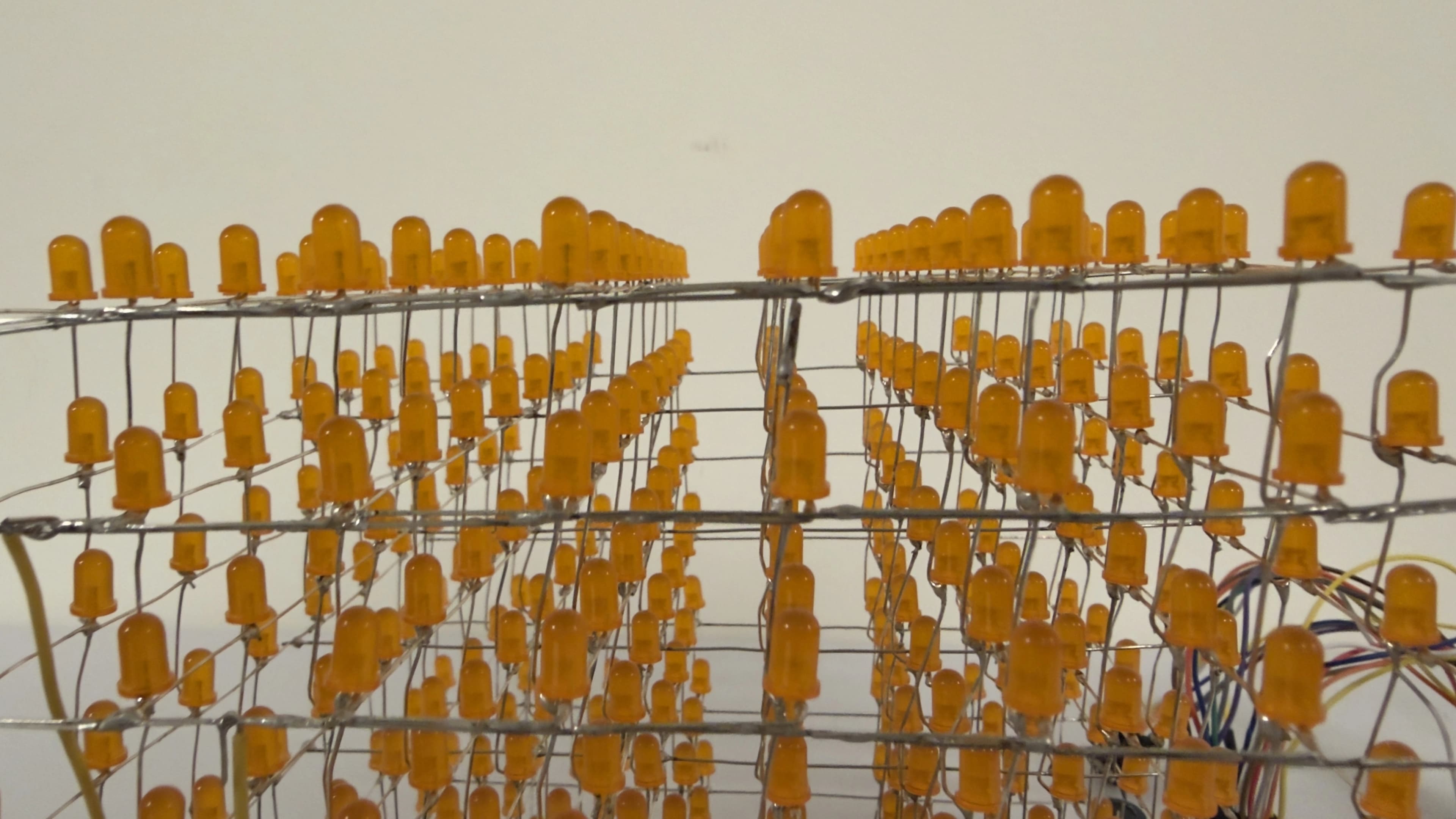
Andrea quickly realized this meant we needed a custom base for the cube, to which I replied:
"I'll make a custom PCB, with perfect spacing plus room for any components we need. With JLCPCB, I can also get it here within a week."I think, at this point, Andrea realized he wasn't getting me out of this totally absurd project that would cost us far more than the reimbursement available. Start brainstorming a price now, I'll tell you later!
component selection
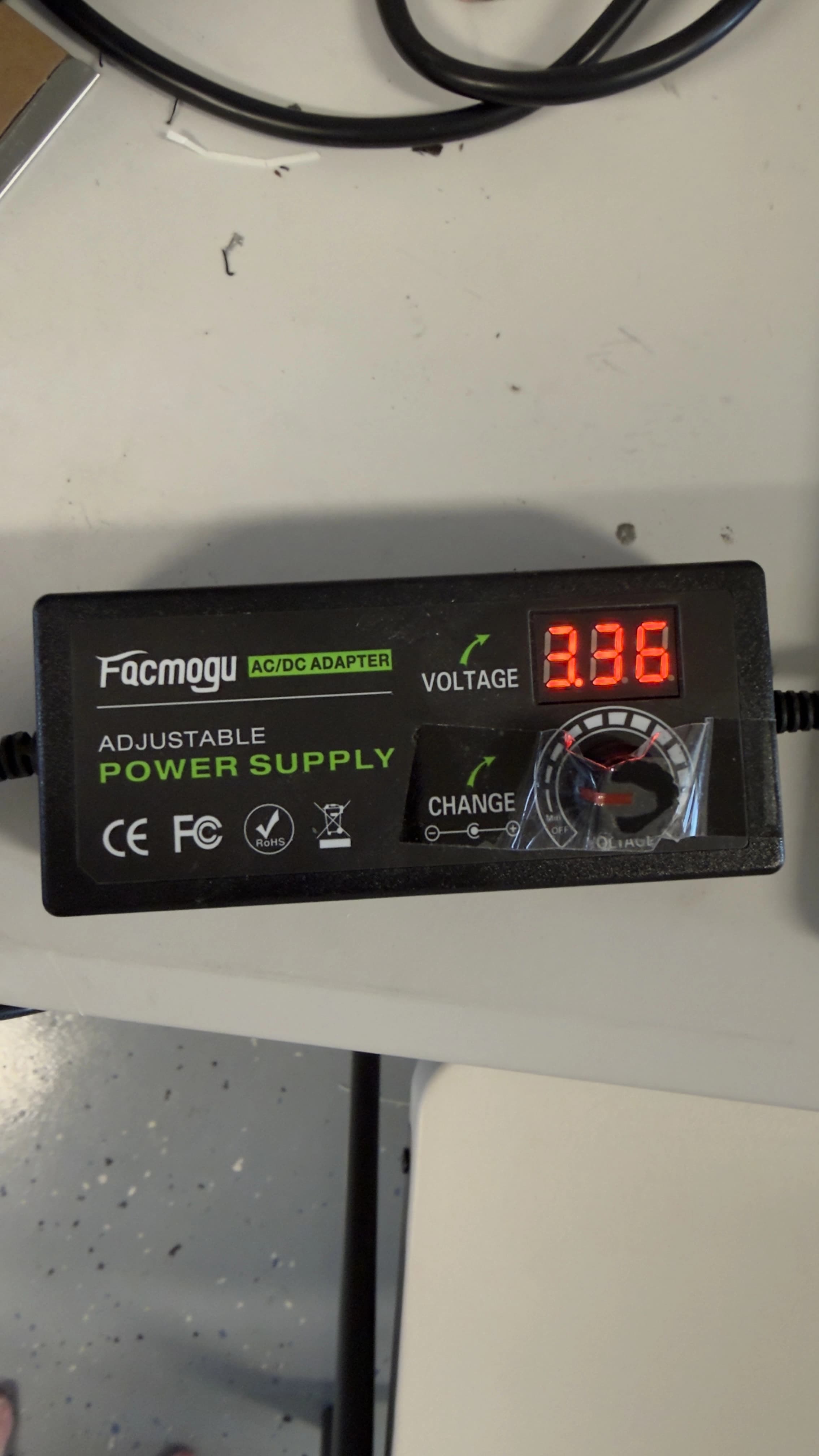
I'll keep this short. We needed to drive the LEDs with far more power than the GPIO could supply, as one fully-ON layer would draw up to 1.6A with the 25mA LEDs we chose. For this, we bought a sketchy variable power supply and pMOS FETs.
The GPIO, however, would die if it tried to sink 1.6A across all of its pins. We needed a seperate IC to handle this, because neither of us wanted to solder 64 transistors. Shift registers were our first thought, but these would ruin any animations because the LEDs would update between frames as we pushed the new data. These also typically can't sink that much current.
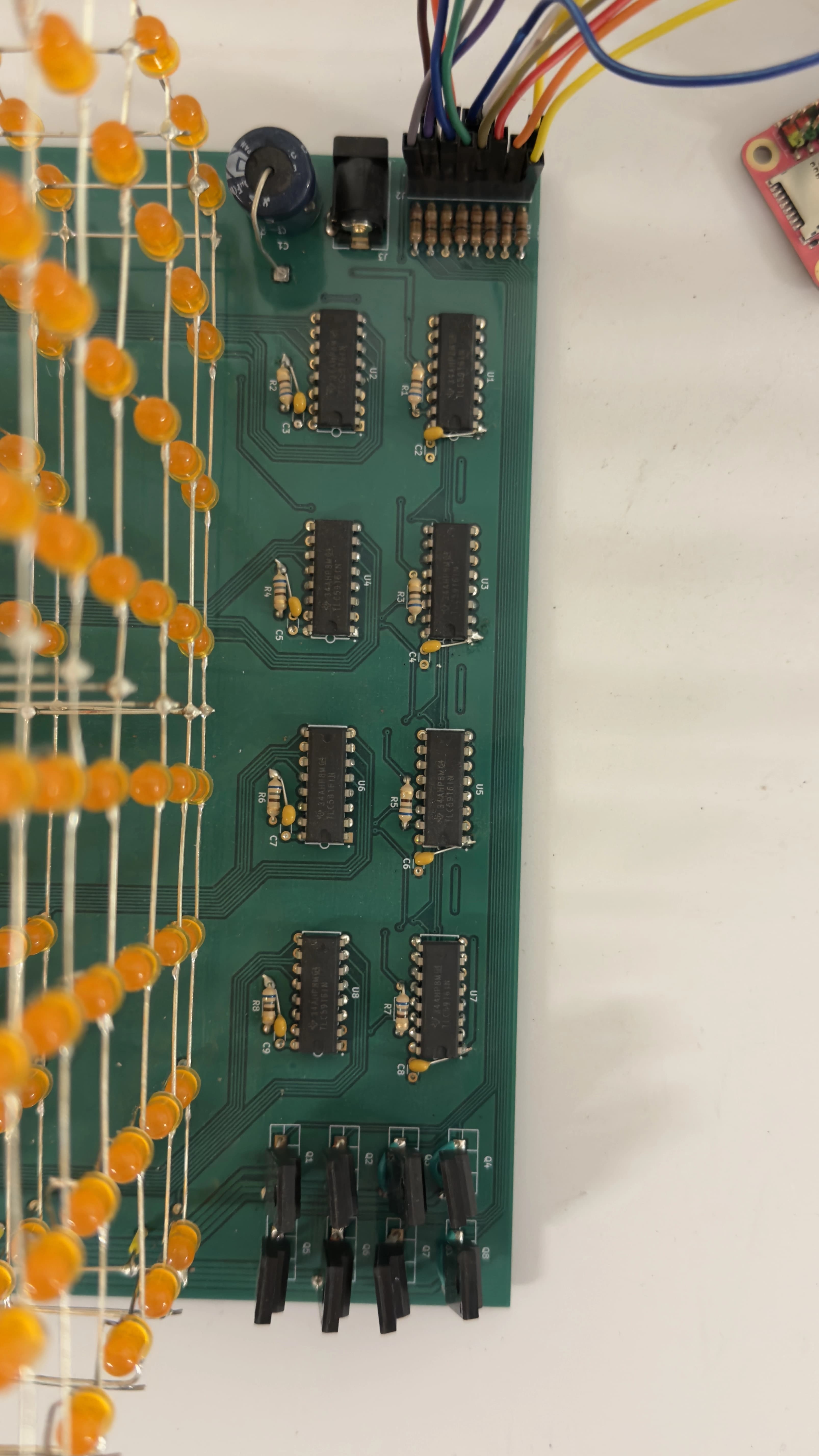
Luckily for us, TI makes chainable automative LED driver ICs that combine a shift register with flip-flops and high-current transistors. With 8 outputs each, we only required 8 of these.
After this, we just needed small decoupling capacitors, a header for plugging in GPIO, a barrel jack, and one fat 1000µF decoupling capacitor. We eneded up stealing that last one from a makerspace.
pcb design
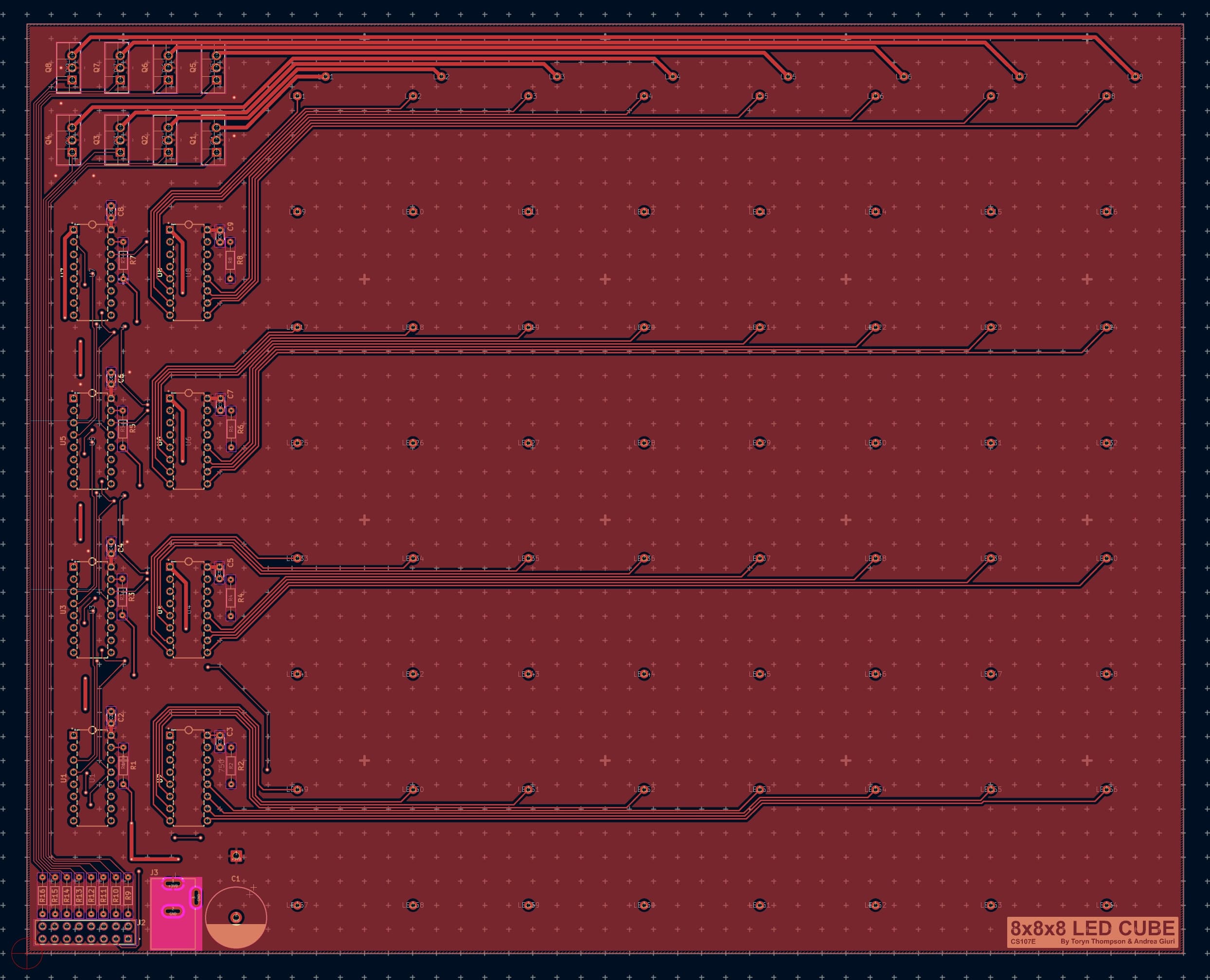
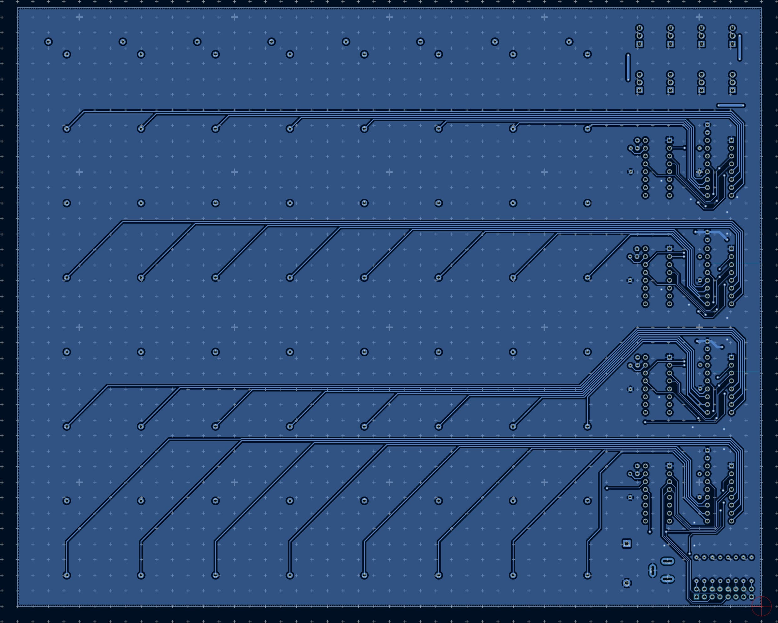
This was a simple, quick, and dirty design I made. The focus was speed because we needed the PCB in one week. If sleep-deprived me made a couple mistakes or had messy traces, it would be fine.
The PCB ended up being around 200x250mm with a 24mm pitch between the grounds. I used the most basic JLCPCB fabrication capabilities in my design rules, ensuring I could order with a 24hr turnaround.
making the cube
Making the cube was by far the most painful part of this project. Soldering 512 LEDs together and aligning them is an intense task.
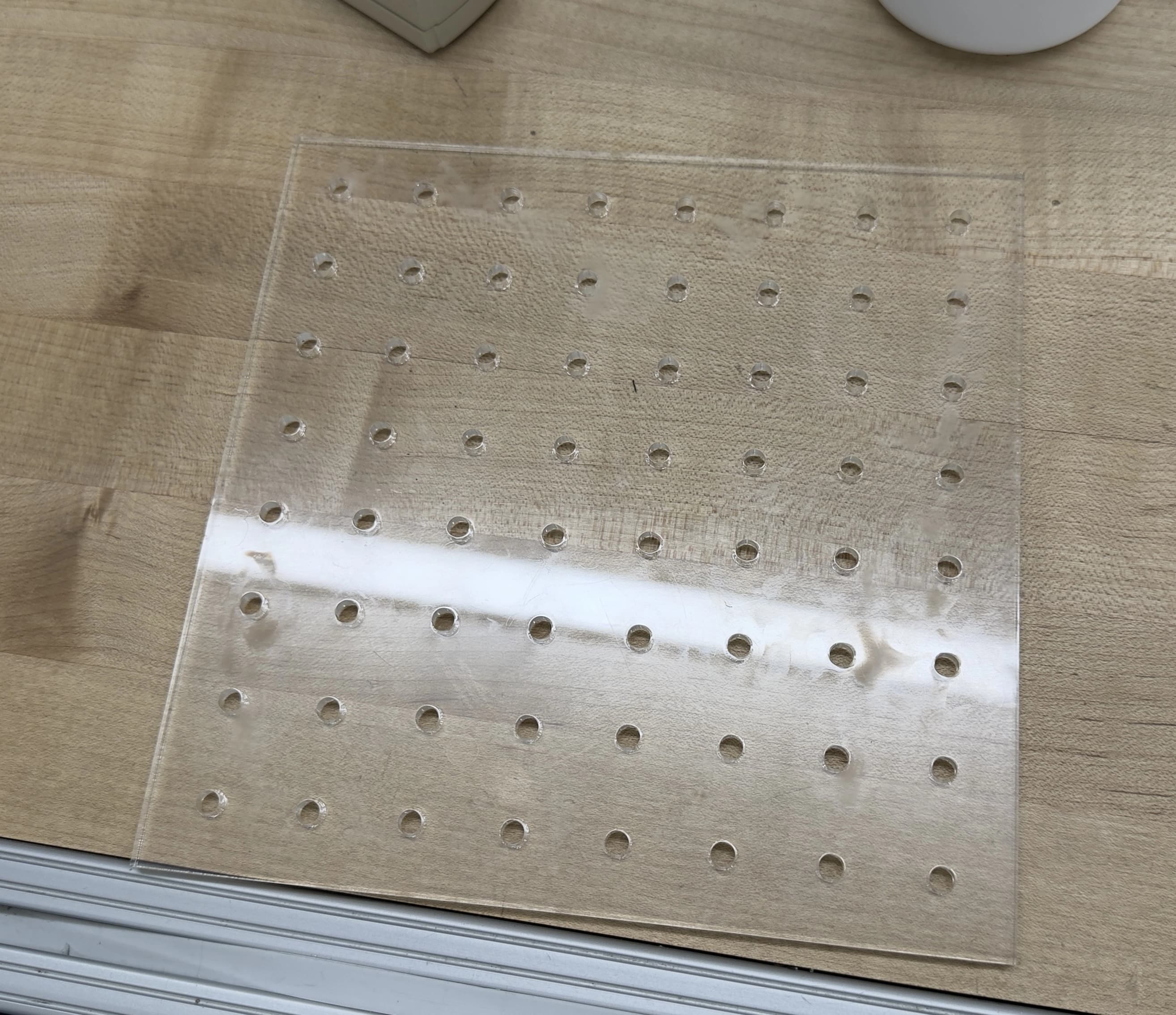
I began by measuring the diameter of our LEDs, then laser-cutting a piece of acrylic to act as a jig for creating each layer.
I then built the first layer. I bent LED leads, keeping the cathode straight and aligning the anodes together into rows. After soldering the andoes together and adding wires bridging the rows, which brought electrical connectivity and mechanical strength, the layer was done!
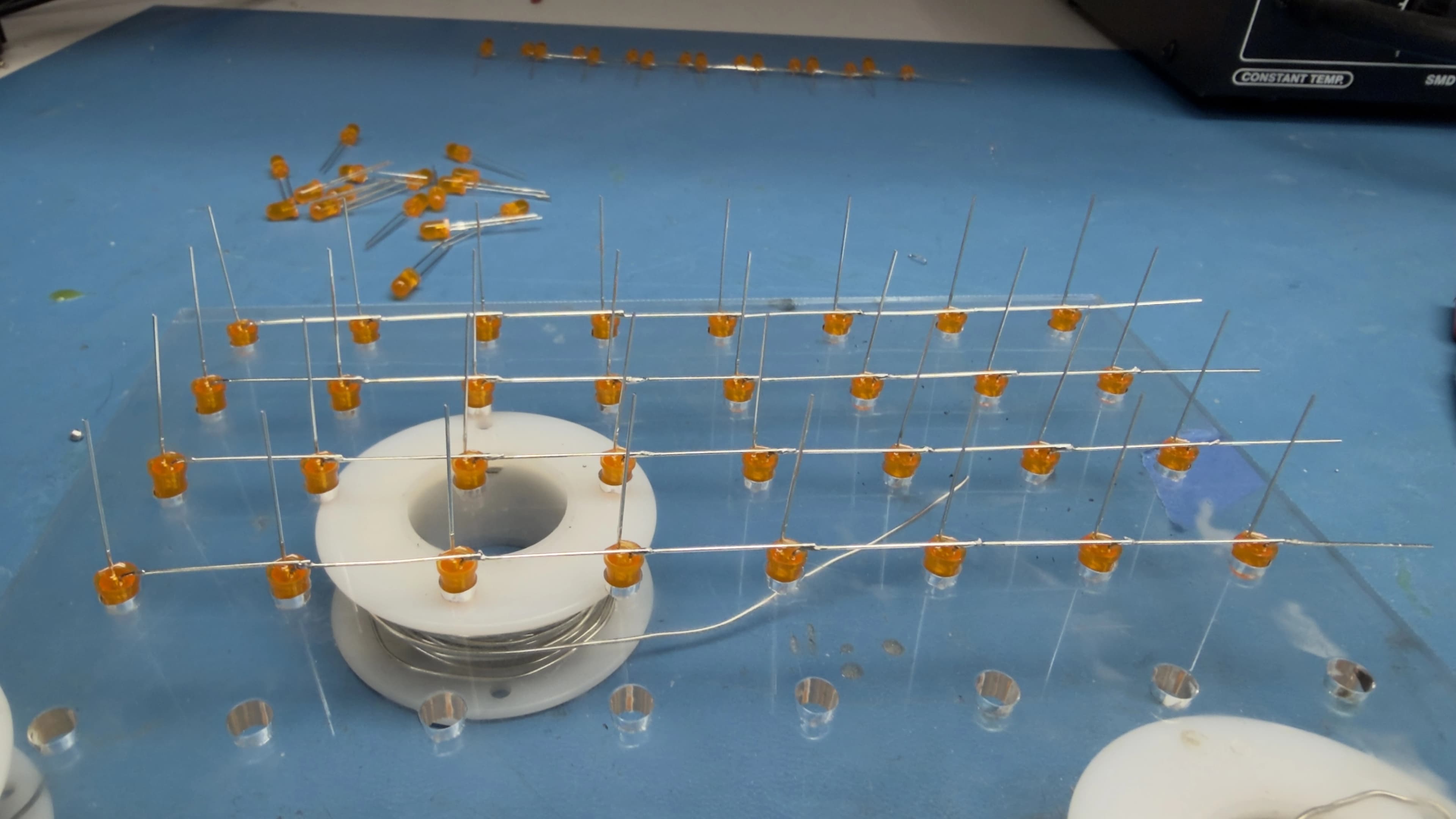
As I went, I would also test the LED rows, as LEDs don't have a perfect yield rate:
I repeated this 8 times over the next day until all layers were ready to be merged vertically.
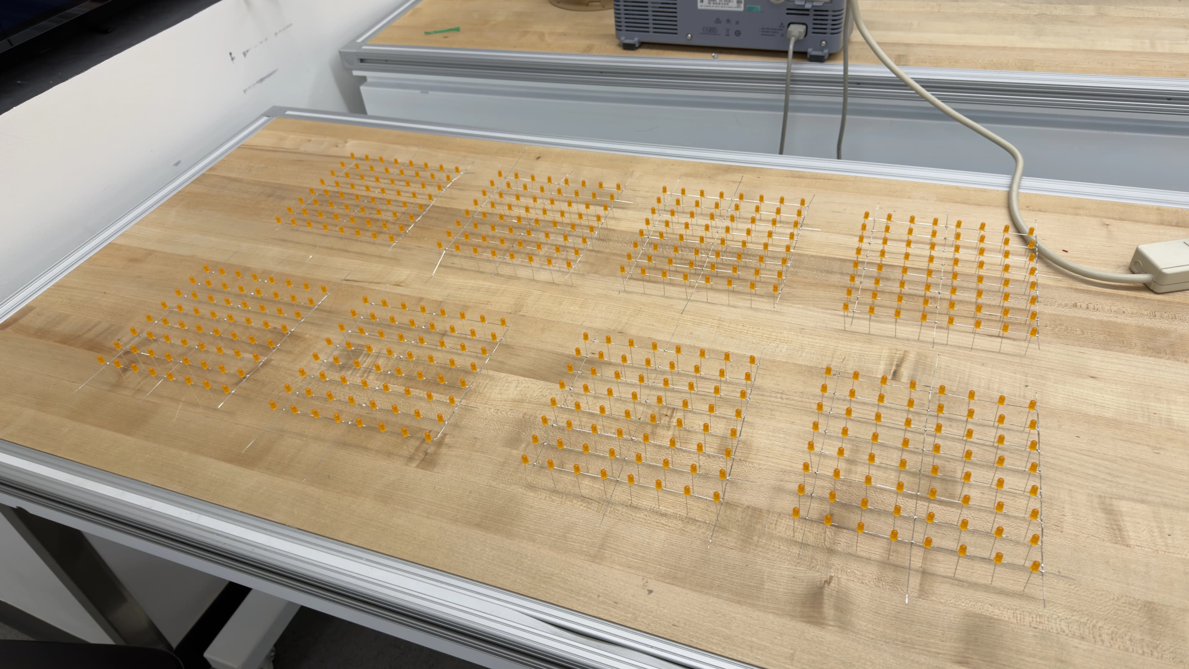
However, merging the layers presented a problem. I needed a way to hold the next layer above the previous by the length of cathode leads, minus a few millimeters for soldering margin. Luckily, Stanford has a large supply of community 3D printers; I could just print a rectangle with the perfect height!
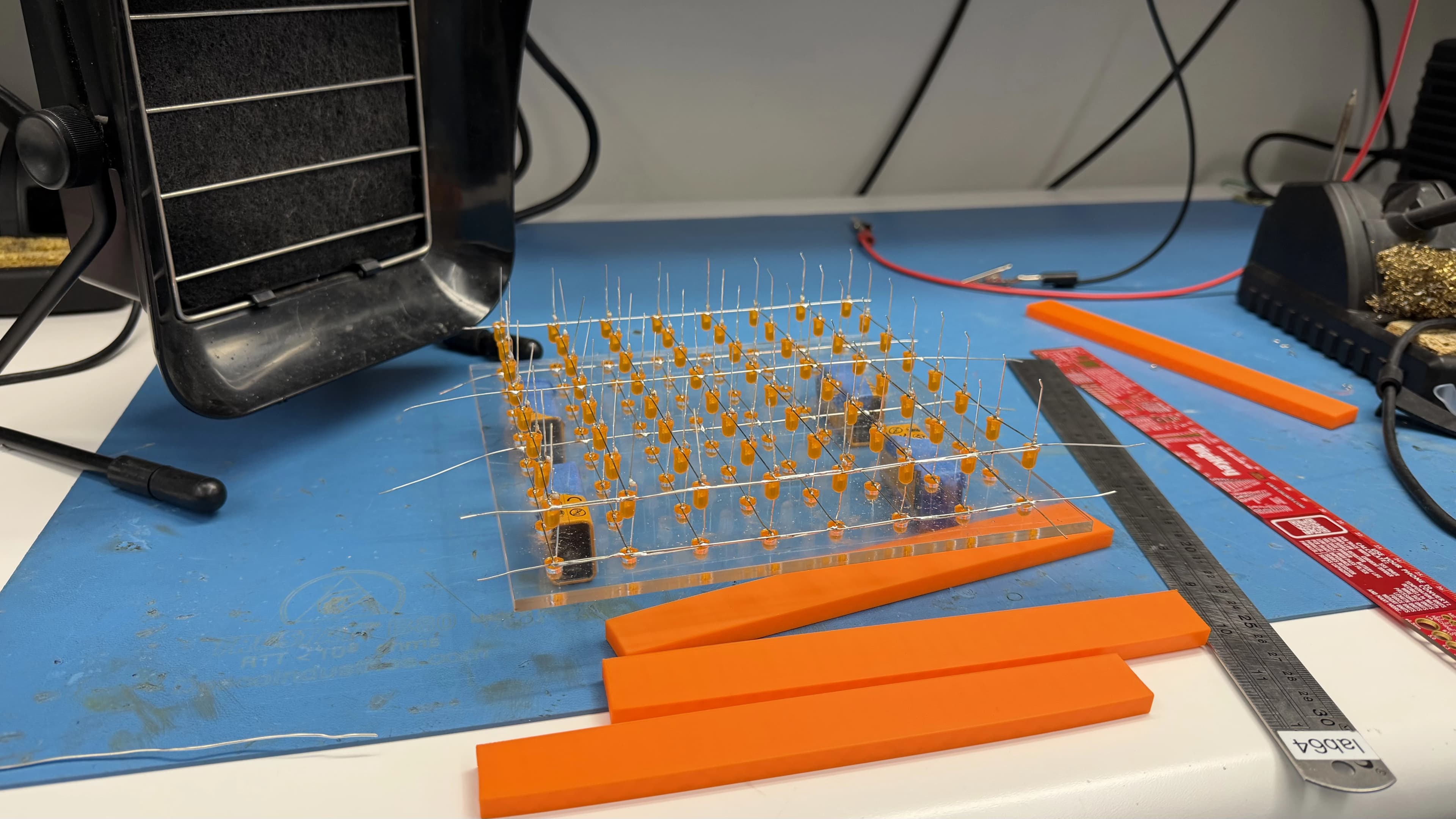
Little did I know, merging the layers would be a very painful experience. I not only had to solder each LED joint with little space for the iron, but also align the LEDs, and moving 1 LED would bend 3 others out of place. Because our PCB arrived just a few days before the project demo day, I has to pull an all-nighter.
Here is a beautiful picture of Stanford in the early morning, after my all-nighter:
The cube was finished the night before demo day. Along with it, the components were soldered onto the PCB, giving us one night to test and finish the software we'd been building in parallel.
software
CS107E uses a MangoPi for embedded development. This uses the Allwinner D1 chip, which has extensive documentation about its peripherals and capabilities. This made software development a little less scary than it could've been. Here is the stack we designed:
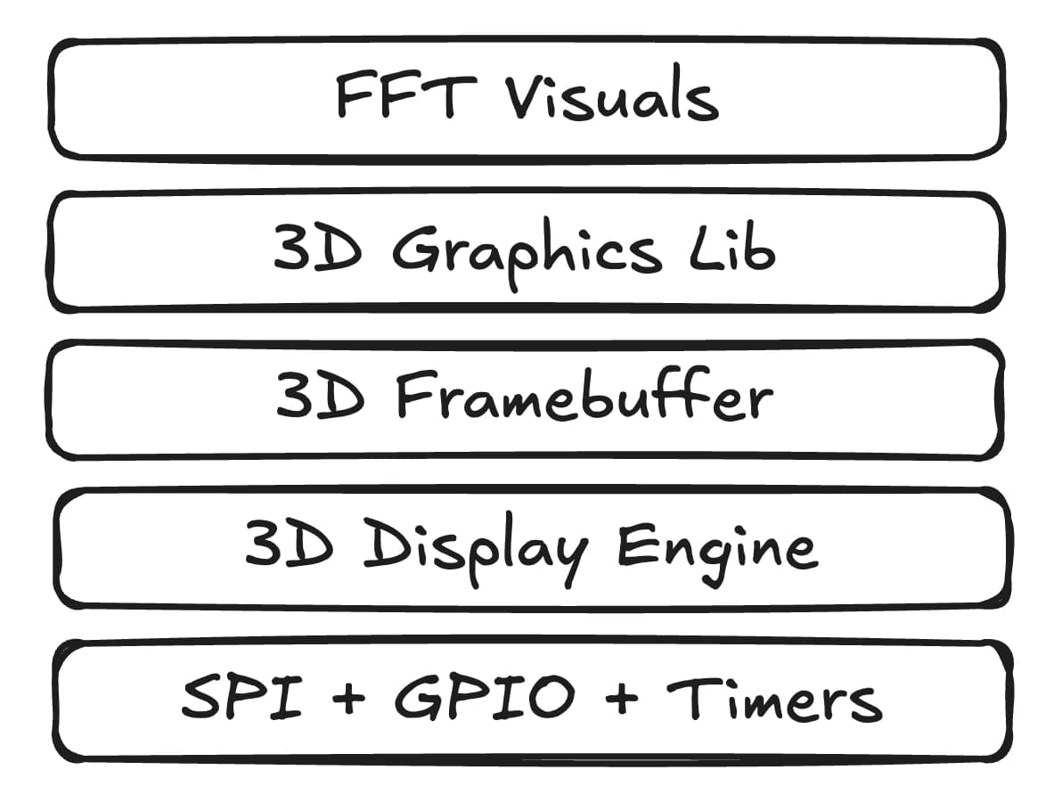
We needed the additional GPIO and timers for generating clock signals responsible for changing flip-flop output, as well as an external button that would switch the visualization between any we created. SPI was used since its TX and RX is just shift registers, so a 8-byte TX would fill our chain of shift registers.
This pipeline is very segmented on purpose, as this allowed us to conduct unit testing and change functionality without sifting through lots of code. We would end up needing to do this when the mapping in our 3D buffer didn't align with the cube.
At a high level, the FFT algorithm takes in sound data passed from our I2S driver, which uses the DMA to buffer 1024 samples from our external microphone without blocking. FFT is then run, with its output placed into 8 frequency bins spanning 0-6KHz. These bins do not have equal bandwidth, as they are logarithmically spaced to better represent distinct areas in our chosen frequency spectrum. Humans hear in octaves, and each of the 8 bins represents one. After, we apply a low pass to each bin that minimizes flicker caused by ambient noise, followed by a normalization based on the bin's bandwidth and the frequency response of our microphone.
This data is now our baseline volume data, and we transform it in different ways depending on the visualization. For the frequency chart, we use the natural log, rounding, and clamping to project volume onto 8 LEDs of height. For the planets, we do something similar, but it alters the radii of the planets, brightness of the bottom plane, and brightness of select LEDs chosen as "stars" in the top plane. Our volume data is applicable to any visualization.
However, we soon realized the visuals felt a bit choppy; we wanted the animations smoother. For this, we converted our 3D framebuffer from a bitmask to a "voxel" of sorts. Each LED is represented by a value of 0-25 in the array, with 0 being OFF and 25 being the maximum brightness. If you remember the math from the ideation section, this indicates each frame is played 25 times. This means 84µs and 2ms, so the dimmest LED is on for 84µs, and the brightest 2ms. The result was great; much cooler looking visualizations!
There are many smaller details regarding the software that I won't go over here for length's sake. If you're curious, the code is on GitHub. Keep in mind this was written in around 2 days, so excuse any mess.
final product
Here is a complete demo of the final cube, complete with me switching between the different visualizations. Unfortunately, the button we used to switch views wasn't there when I filmed this, so I short the wires manually:
The planet visualization is difficult to see on video, but it has the bottom plane of LEDs representing the bass via brightness, planets changing radius for the mids, and stars appearing on the top plane for highs.
The cube costed around $250 in total, but was totally worth it! Just look at how cool that thing is!